
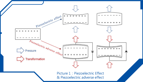
1.The quartz blank is a piezoelectric material, the electric field is generated by applying an external voltage on both sides of the blank, due to the mechanical and electrical coupling of the piezoelectric material itself, the crystal generates mechanical deformation, the cutting surface of the crystal is subjected to mechanical stress, and the two opposite surfaces of the crystal will generate an electric potential difference, this characteristic is called the piezoelectric effect. When we apply an AC voltage to the crystal, a cyclical wafer vibration can be generated; the frequency of vibration will vary from different crystals, the thinner the quartz crystal cutting disc, the more difficult the cutting technique, but the higher the resonance frequency.
2.The piezoelectric effect of quartz crystals: when pressure is applied to the crystal axis, electrical changes will occur on the quartz plate; on the contrary, when pressure is applied to the quartz plate, the inside of the quartz crystal will be deformed and twisted, it is called the piezoelectric effect of quartz crystal (as below figure 1). “When the force is deformed, a polarization phenomenon occurs inside, and at the same time, different charges are generated on the two surfaces. After the external force is removed, it returns to an uncharged state. This is called the piezoelectric effect. When the direction of the force changes, the polarity of the charge changes accordingly. This phenomenon is called the "positive piezoelectric effect." On the contrary, when an electric field is applied in the polarization direction of the dielectric, these electrolytes will also produce geometric deformation. This phenomenon is called the " piezoelectric adverse effect”.
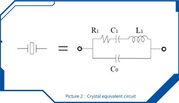
3.Crystal Equivalent Circuit: composed of motional capacitance C1, dynamic inductance L1, series resistance R1, and static capacitance C0. Picture 2 shows the equivalent circuit diagram of a crystal unit to explain the basic elements that are responsible for the characteristics and performance of this electronic component; the first three parameters are called the "dynamic parameters" of the crystal unit.
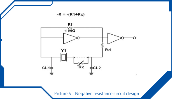
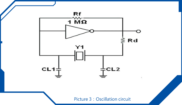
1.A parallel oscillating circuit uses a crystal unit. The working center frequency of this crystal unit is tuned by means of a specified load capacitance value.
2.The other oscillating path uses an inverter and two capacitors (CL1, CL2) serves as the receiving circuit; the combination of the two capacitors results in the load capacitance that causes together with the crystal unit the oscillation frequency.
3.Rf in the oscillation circuit is a so-called feedback resistor.
4.Rd in the oscillating circuit is a damping resistor; the value of this resistance has a big influence on the current drive level through the crystal unit. It has to be properly chosen to create a stable oscillation of the crystal unit.
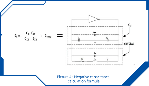
1. Load capacitance
In order to stabilize the frequency in an oscillator circuit a crystal unit typically works as inductor while other components of the circuit are connected in series or in parallel leading to the load capacitance. Different load capacitance values may affect frequency deviation. Therefore, it is recommended to measure the effective load capacitance in the application to clarify the necessary load capacitance that has to be used to make the correct frequency adjustment during the xtal production process.
The calculation of load capacitance is as follows picture 4.
Note: stray capacitance means factors such as stray value included in IC, capacitance between leads and traces, parasitic capacitance in each layer of PCB board etc.
2. Negative Resistance
In order to stabilize the oscillation circuit, the designer can refer to the above circuit to test the negative resistance on the board; connect one side of crystal to a variable resistor (VR). When the value of the variable resistor (VR) reaches a certain resistance value, the crystal stops vibration, this value is negative resistance (-R); generally, the recommended value of negative resistance (-R) is the internal resistance of the oscillator more than 3 times to meets the design circuit of the negative resistance.